 Ultimate guide
Structural Retaining Wall Design Requirements: A 2026 Guide
Table of Contents
- What Structural Retaining Wall Design Requirements Cover
- When Your Retaining Wall Needs Structural Engineering Design
- Site Assessment and Soil Conditions for Retaining Wall Design
- Retaining Wall Drainage Design and Hydrostatic Pressure Control
- Retaining Wall Surcharge Loads and Lateral Earth Pressure
- Retaining Wall Stability Checks and Design Verification
- Retaining Wall Design Plans, Certification, and Permits
- Building Codes, Australian Standards, and Council Approval
- Frequently Asked Questions
Last Updated: October 14, 2026
What Structural Retaining Wall Design Requirements Cover
Structural retaining wall design requirements define the engineering standards, safety checks, and documentation needed to ensure a wall safely contains soil and resists the forces acting on it, from site assessment through certification.
The scope covers geotechnical investigation, structural calculations (lateral earth pressure, stability checks, foundation sizing), drainage design, and compliance with AS 4678 and relevant building codes. Each element addresses a failure mode: poor drainage pushes the wall outward, missed surcharge loads cause sliding or tipping, and weak foundations cause settlement and cracking.
At AK FENCING VIC PTY LTD, we work with structural engineers to ensure every retaining wall project meets these requirements before installation begins, protecting your property and ensuring the wall performs for decades.
When Your Retaining Wall Needs Structural Engineering Design
Not every retaining wall needs a structural engineer. Small garden walls are often exempt, while walls retaining a surcharge, sitting on a boundary, or exceeding a height threshold normally need engineered design and certification.
Three questions decide whether engineering is needed: does the wall need development approval, a building permit, and structural certification? A wall can need one and not the others.
Height and approval thresholds by jurisdiction
The table below summarises the general position. Treat it as a starting point only, because councils can impose stricter controls on flood-prone, coastal erosion, heritage, and bushfire-prone land.
| Jurisdiction | Typical exempt height for a non-engineered wall | When engineering and certification are normally triggered |
|---|---|---|
| New South Wales | Generally under 600 mm, and not on a boundary or within a foreshore or flood area | Walls 600 mm and above, or any wall on or near a boundary, usually need a building permit and structural certification |
| Victoria | Generally under 800 mm for a garden wall not supporting a surcharge | Walls 800 mm and above, or any wall supporting a building, driveway or neighbouring land, normally need a building permit and engineering |
| Queensland | Generally under 1 m, and not within 1.5 m of a boundary or building | Walls 1 m and above, or within the boundary setback, usually need building approval and engineering |
| Western Australia | Generally under 500 mm for a free-standing garden wall | Walls 500 mm and above, or any wall retaining a surcharge, typically need a building permit and certification |
| South Australia | Generally under 1 m, and not on a boundary | Walls 1 m and above, or on a boundary, normally need development or building approval and engineering |
| Tasmania | Generally under 1 m, and not on a boundary | Walls 1 m and above, or on a boundary, normally need a building permit and engineering |
| Australian Capital Territory | Generally under 1 m, and not on a boundary | Walls 1 m and above, or on a boundary, normally need a building approval and engineering |
| Northern Territory | Generally under 1 m, and not on a boundary | Walls 1 m and above, or on a boundary, normally need a building permit and engineering |
The triggers that override a height exemption
Even a wall below the exempt height will usually need engineering if any of the following apply:
- The wall retains a surcharge, such as a building, driveway, car park, pool, or stockpile
- The wall sits on or within the boundary setback distance of a property boundary
- The wall is on a slope steeper than about 1 in 4, or forms part of a tiered wall system
What the engineering package actually contains
When engineering is required, the deliverable is a set of signed, dated documents a certifier can assess:
- A site plan showing the wall alignment, height, length, and distance to boundaries and structures
- Cross-sections at critical locations, with wall dimensions, reinforcement, and footing details
- A geotechnical report or a documented soil assessment with design parameters
If any document is missing, the certifier will usually refuse the permit and the builder cannot legally start work. Preparing the package costs far less than remediating a failed wall, which can run into tens of thousands of dollars.
At AK FENCING VIC PTY LTD, we coordinate the geotechnical investigation, structural engineering, and certification so the approval package is complete before construction begins.
Site Assessment and Soil Conditions for Retaining Wall Design
Site assessment is the foundation of sound retaining wall design.
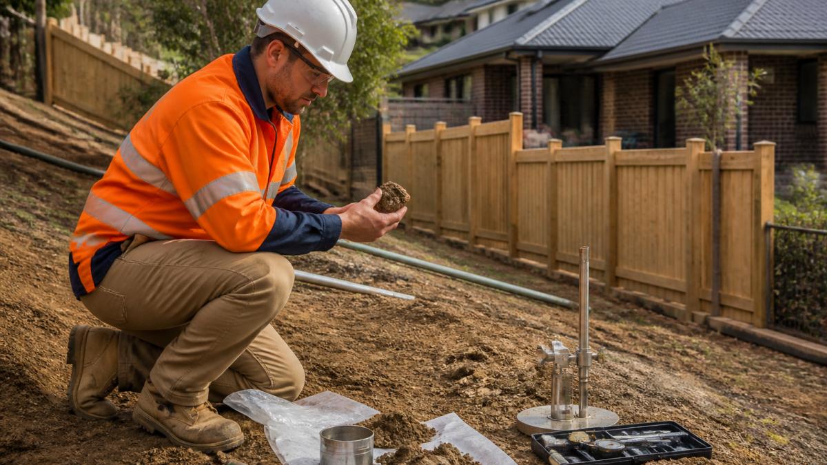
Soil conditions directly determine lateral earth pressure, the horizontal force pushing against the wall. Sandy soils exert higher lateral pressure than cohesive clays, and poorly compacted fill exerts much higher pressure than undisturbed soil. A geotechnical investigation typically involves:
- Borehole drilling and soil sampling at multiple depths
- Laboratory testing of soil samples (grain size, moisture, density, shear strength)
- Assessment of groundwater table location and seasonal variation
The engineer uses this data to calculate design earth pressure (often using Rankine or Coulomb theory), which determines wall thickness, reinforcement, and foundation depth.
Retaining Wall Drainage Design and Hydrostatic Pressure Control
Drainage is critical to retaining wall longevity and safety. Water trapped behind the wall creates hydrostatic pressure that can exceed lateral earth pressure alone, pushing the wall outward and increasing failure risk.
Retaining wall drainage design typically includes:
- Drainage layer: A permeable material (gravel, geotextile-wrapped drainage composite) placed directly behind the wall to intercept water flowing through the retained soil
- Weep holes or perforated pipes: Outlets in the wall base or lower courses to allow trapped water to escape
- Subsurface drainage: A perforated pipe (French drain) at the wall base, sloped to direct water away from the site
Design life depends heavily on drainage. Walls with inadequate drainage typically show seepage, efflorescence, bulging, or cracking within 5-10 years; proper drainage extends design life to 50+ years.
Retaining Wall Surcharge Loads and Lateral Earth Pressure
Surcharge loading is additional weight on the soil behind the wall, a building foundation, driveway, stockpile, or parked vehicles. This weight increases lateral earth pressure significantly and must be accounted for in the structural design.
A building foundation 2 metres from a retaining wall can increase lateral pressure by 50% or more. A driveway directly above the wall creates even higher pressure. The engineer calculates surcharge loads based on:
- Building weight and foundation location
- Vehicle loads (for driveways or parking areas)
- Temporary construction loads (equipment, materials during filling)
Failure to account for surcharge loads is a common design error: walls designed for soil pressure alone may fail when a building is constructed nearby.
Retaining Wall Stability Checks and Design Verification
Stability checks prove the wall will not slide, tip, or sink under the design loads, closing the loop between site investigation, load assessment, and final detailing.
The design workflow, step by step
A typical structural design for a retaining wall follows this sequence:
- Site investigation. The geotechnical engineer drills boreholes or test pits, samples the soil, and logs the groundwater table, producing a soil profile with design parameters.
- Soil parameter selection. The engineer selects a friction angle (φ), cohesion value (c), unit weight (γ), and allowable bearing pressure, the inputs to every subsequent calculation.
- Load assessment. The engineer calculates lateral earth pressure from the retained soil, adds surcharge from buildings, vehicles, or stockpiles, and adds water pressure if drainage is not fully effective.
- Stability checks. The engineer tests the wall against sliding, overturning, and bearing failure, adjusting geometry, embedment, or reinforcement until each check passes with the required factor of safety.
- Structural design of the wall element. For concrete, the engineer sizes reinforcement for the bending moment and shear force from lateral pressure; for segmental block, they check block and geogrid capacity.
- Drainage and detailing. The engineer specifies the drainage layer, weep holes or perforated pipe, geotextile, and backfill, and details connections and construction sequence.
- Documentation and certification. The engineer issues the drawings, calculations, specifications, and certification statement.
Worked concept: lateral earth pressure
For a simple, drained, cohesionless backfill, the active earth pressure coefficient using Rankine theory is Ka = (1 − sin φ) / (1 + sin φ).
If the same wall retains saturated soil with no drainage, water adds a full hydrostatic pressure of 9.81 kPa per metre of depth. At 3 m, that is an extra 29.4 kPa at the base, and the resultant water force alone is about 44 kN per metre, larger than the soil force.
Worked concept: sliding, overturning, and bearing
Using the same 3 m wall, assume the wall and footing weigh 60 kN per metre and base friction is 0.45.
- Sliding. Resisting force = 60 × 0.45 = 27 kN. Driving force = 27 kN. Factor of safety = 1.0, which fails. The engineer must increase base width, add a shear key, or use a geogrid-reinforced soil mass to raise the resisting force. A common target is a factor of safety of at least 1.5 under service loads.
- Overturning. The resisting moment is wall weight times the lever arm from the toe; the driving moment is the lateral resultant times its height above the base. If resisting moment is 90 kN·m and driving moment is 54 kN·m, the factor of safety is 1.67, passing a typical 1.5 target.
- Bearing. The resultant of vertical and horizontal forces must fall within the middle third of the base to avoid tension under the footing, and maximum bearing pressure must stay below the allowable bearing capacity from the geotechnical report. If allowable capacity is 150 kPa and the calculated maximum is 180 kPa, the footing must be widened or the wall lightened.
These three checks interact. Widening the base to fix sliding also increases the resisting moment for overturning and reduces bearing pressure, but adds weight and cost. The engineer's job is to find the geometry that satisfies all three with the least material.
Additional checks that often govern
- Global slope stability. For walls on or near a slope, the engineer checks that the whole slope, not just the wall, is stable, often the governing check on hillside sites.
- Internal stability of reinforced soil. For geogrid walls, the engineer checks the soil-reinforcement bond is sufficient to prevent pull-out.
- Seismic loading. Where seismic design applies, the engineer adds a pseudo-static horizontal force and re-runs the stability checks.
What the calculations should document
A well-prepared calculation set records design assumptions, soil parameters and their source, load combinations, factors of safety, the method used, and the results of each check, plus what was not checked and why. That record lets a certifier, future owner, or forensic engineer understand the design basis if anything goes wrong.
At AK FENCING VIC PTY LTD, we work with structural engineers who document each stability check and provide the calculation set with the certification, so the design is transparent and defensible.
Retaining Wall Design Plans, Certification, and Permits
Engineering plans and certification translate design calculations into a buildable structure and satisfy council requirements. Plans include:
- Site plan showing wall location, height, length, and proximity to structures and boundaries
- Cross-section drawings with wall dimensions, materials, reinforcement, and foundation details
- Drainage design and outlet locations
Structural engineer certification confirms the design meets relevant standards and is fit for purpose. It is typically required before building permits are issued and is backed by professional indemnity insurance.
Without certified plans, councils will not issue permits and builders cannot legally proceed. If the wall fails, the engineer's certification provides legal protection and a path to recovery if negligence is involved.
Building Codes, Australian Standards, and Council Approval
Retaining wall design in Australia is governed by the National Construction Code (NCC), which references Australian Standard AS 4678 Earth-retaining structures.
Local councils enforce the NCC and may add requirements based on local geology, flooding risk, or development patterns. Some require geotechnical reports for all walls over 1.5 metres; others have lower thresholds. Approval processes vary:
- Development approval: Required for walls in some jurisdictions or if the wall triggers planning requirements (e.g., a wall that changes site drainage or affects neighbouring properties)
- Building permit: Required for most engineered walls; typically issued after plans are certified by a structural engineer
- Inspection and sign-off: Most councils require on-site inspection during and after construction to verify compliance with approved plans
Council approval timelines range from 2-4 weeks for straightforward applications to 8-12 weeks for complex sites.
Non-compliance can result in enforcement notices, stop-work orders, or requirements to remove or remediate the wall.
At AK FENCING VIC PTY LTD, we coordinate with structural engineers and councils throughout the design and approval process.
Retaining wall design requirements exist to prevent failure, protect neighbouring properties, and ensure your wall performs reliably for decades. Contact us for a free quote and site assessment.
Frequently Asked Questions
When does a retaining wall need structural engineering design?
Any retaining wall over 1 metre in height, or walls subject to significant surcharge loads from buildings, vehicles, or nearby structures, requires engineering design by a qualified structural engineer. Walls retaining unstable soil, those in flood-prone areas, or any wall where failure could damage property or endanger life must be designed and certified. Your local council can advise whether your specific project requires engineering certification based on site conditions and wall height.
What is AS 4678 and why does it matter for retaining wall design?
AS 4678 is the Australian Standard for earth-retaining structures. It sets minimum design requirements for stability, durability, and safety. Compliance with AS 4678 is mandatory for engineered walls and ensures your design accounts for soil properties, lateral earth pressure, drainage, and construction quality. Your structural engineer will design to this standard and certify compliance. Non-compliance can lead to council rejection of your development approval and structural failure.
How does retaining wall drainage design prevent failure?
Hydrostatic pressure builds when water accumulates behind a retaining wall, dramatically increasing lateral earth pressure and risk of sliding or overturning. Proper drainage design includes perforated pipes, granular backfill, and surface water management to remove water before it builds pressure. Without effective drainage, even well-designed walls can fail. Your structural engineer must specify drainage requirements in the engineering plans, and the licensed builder must install drainage correctly during construction.
What loads must be considered in retaining wall design?
Design must account for lateral earth pressure from retained soil, hydrostatic pressure from groundwater, surcharge loads from buildings or vehicles near the wall, and the wall's own weight. Each load type affects stability differently. Lateral earth pressure depends on soil type and retained height; surcharge loads depend on proximity and weight of nearby structures. Your structural engineer calculates all loads during site assessment and incorporates them into the design to ensure the wall resists sliding, overturning, and bearing capacity failure.
What are the main stability checks for a retaining wall?
Three critical stability checks verify a retaining wall design: sliding (will the wall slip along its base?), overturning (will it tip forward?), and bearing capacity (will the foundation soil compress or fail?). Engineers also check for retained soil movement and ensure the design life matches your requirements. Each check uses engineering calculations based on soil conditions, wall geometry, and applied loads. Your structural engineer documents all checks in the engineering certification, which council and the licensed builder use to verify compliance.
What information must be included in retaining wall engineering plans?
Engineering plans must show wall geometry, foundation depth and width, reinforcement layout, drainage details, soil profile and geotechnical data, applied loads, design calculations, stability check results, material specifications, and construction tolerances. Plans must be signed by the structural engineer and include a statement of design compliance with AS 4678. Council uses these plans to assess your development approval; the licensed builder uses them to construct the wall correctly. Incomplete or unclear plans will delay approval and risk construction errors.
Do I need council approval before building a retaining wall?
Most councils require development approval for retaining walls over 1 metre, walls on boundaries, or walls where failure could affect neighbouring properties or public land. Some councils exempt smaller walls or walls built entirely on your own land away from boundaries. You must check your local council's requirements before design begins. Approval typically requires engineering plans, site assessment data, and proof of structural certification. Building without required approval can result in enforcement action and costly remediation.
What is the difference between a gravity wall and an engineered wall?
A gravity wall relies on its own weight to resist lateral earth pressure; common materials include timber, stone, or concrete. An engineered wall uses reinforcement (steel or geogrid) to resist loads more efficiently, allowing thinner or taller designs. All gravity walls over 1 metre and most walls subject to surcharge loads require structural engineering design and certification. Even timber or concrete gravity walls must be designed to AS 4678 and verified by a structural engineer. Your engineer will recommend the most cost-effective solution for your site conditions and height requirements.